Stop action, and beginning of integration
Stop Action
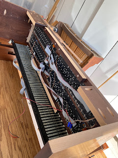
For the St John's practice organ, I'm using some old LRT3 (lighted rocker tablets) actions that I had for my old organ before I upgraded to moving drawknobs. These were pre-USB design from MIDIWorks. The existing interface was cumbersome, and not well documented, so I decided to reverse engineer the rockers and repurpose an existing board from my system to integrate it with the rest of the key and stop scanning system.
The LRT's were simply a diode isolated 4x8 matrix of switches, and a serial shift register to drive the LED's behind the rockers. The 8 on/off switches and 8 LEDs are duplicated into 2 groups. Because there are only a single row of 2.54mm pins, it's easy to put a ribbon cable connector on it. I have a board design (same as in the previous post) where I can allocate 8 port pins on one connector for the D bus and 16 port pins on another connector for the C interface, one set of 16 rockers on the odd pins and one set of 16 rockers on the even pins. Firmware duplicates the CLOCK and STROBE pins for the LED shift registers, and properly puts the data in to the separate chains. I could have forced it into one board, but the cable would have taken forever to make. Much easier to just build another board.
This weekend I was hard at work building the rest of the case. My new favorite tool is a pocket screw jig. Makes building stuff a lot faster, with butt joints going together much more easily than with other joinery. It's not as elegant as a dado or a rabbit, but takes much less time.
The stop jambs are a bit taller than I expected, but kind of in the Schlicker family, should be OK.
Next step is hooking up all the cables and starting the testing. I like to play an instrument I've built for a week or two before sending it off to its forever home to try to find bugs...
Comments
Post a Comment